
Introduction
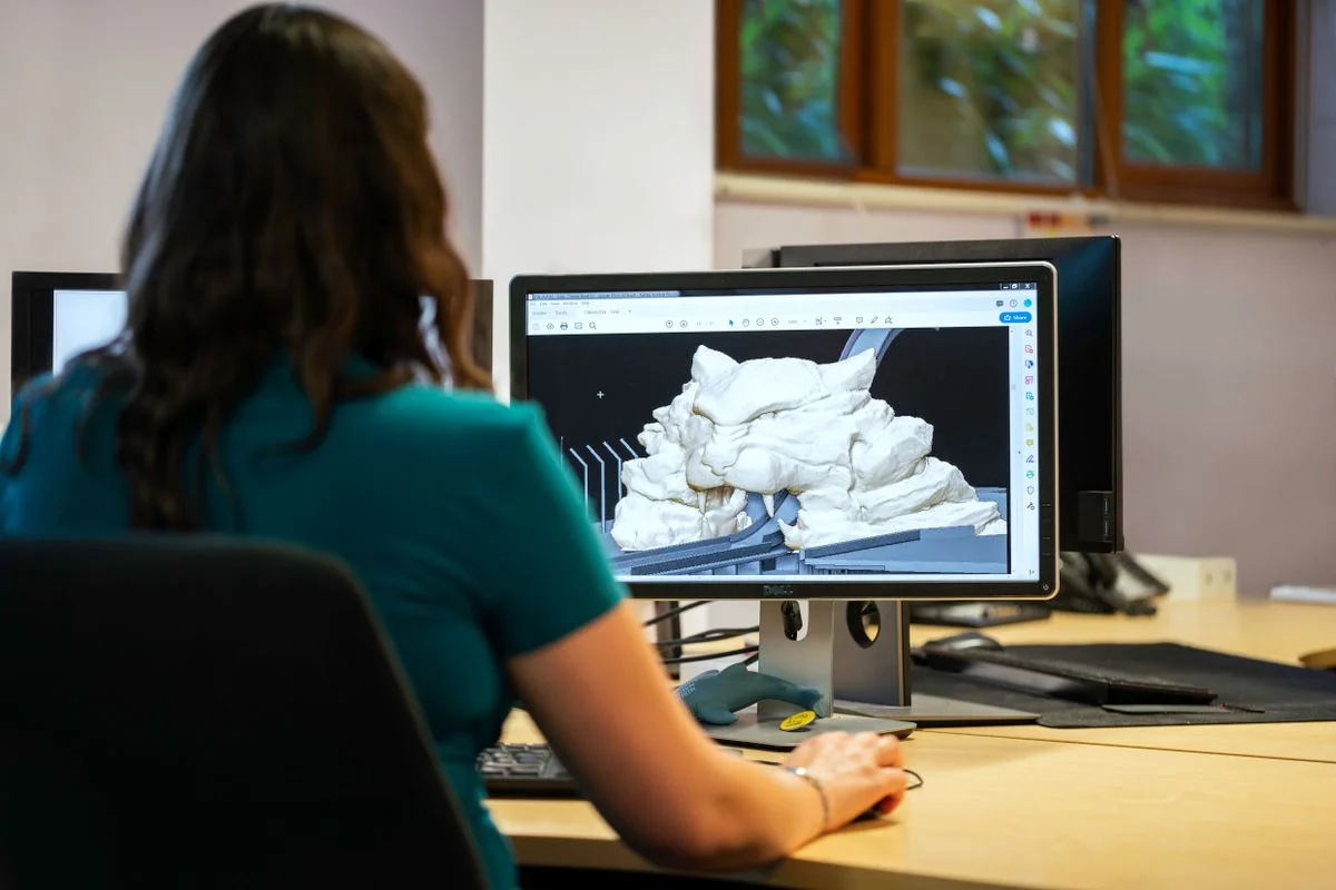
CAD systems in the plastics industry are computer-based design environments used to create, modify, analyze, and document products, tooling, molds, dies, fixtures, and production equipment before physical manufacturing begins. In plastics processing, they are central to product development because they connect part geometry, material behavior, tooling design, and downstream manufacturing workflows into a single digital process.
CAD systems are not limited to simple drafting. They are used for 2D drawings, 3D solid and surface modeling, parametric design, tolerance definition, assembly management, simulation, and data exchange with CAM and CAE tools. In plastics manufacturing, this supports injection molding, extrusion tooling, blow molding, thermoforming, compression molding, and auxiliary equipment design, while also reducing redesign time, prototype costs, and production errors.

Historically, CAD evolved from manual drafting replacement into a broader digital engineering platform that now underpins virtual prototyping, manufacturing automation, and product lifecycle workflows. Current systems increasingly integrate cloud collaboration, simulation, and data handoff to CNC and additive manufacturing processes, making CAD a foundation for Industry 4.0-oriented plastics operations.
Sustainability has also become a major driver. By improving first-time-right design, optimizing material usage, and enabling simulation before tooling is cut, CAD systems can reduce scrap, shorten development cycles, and support resource-efficient plastics production. Looking ahead, the most important developments are expected in generative design, tighter CAD/CAE/CAM integration, and model-based engineering that connects product geometry more directly to process performance and factory automation.
History and Development
Early CAD emerged as a digital replacement for manual drafting, but its role expanded rapidly as computing power improved and engineering data became easier to manipulate electronically. In manufacturing, this shift was especially important for plastic parts and tooling, where small geometric changes can strongly affect flow, cooling, shrinkage, and final part quality.
Key milestones in development include:
- The transition from 2D drafting to 3D parametric modeling, which enabled reusable features, assemblies, and automatic drawing updates when dimensions change.
- The integration of CAE tools for stress, thermal, motion, and flow analysis, allowing designers to evaluate performance before tooling or production.
- The connection of CAD with CAM and CNC systems, which made digital models directly useful for machining molds, dies, and components with less manual re-entry of data.
For plastics processors, this evolution mattered because tooling quality is a major determinant of cycle time, part appearance, dimensional accuracy, and scrap rate. CAD therefore moved from being a drafting aid to being a core engineering system for product and mold development.
Technical Overview
A CAD system typically combines geometric modeling, dimensioning, constraint control, drafting, part libraries, assembly management, and export functions for manufacturing and analysis. In plastics applications, the model is often the master record for the product, the mold or die, and the tooling interfaces required for production.
Core functions
- Geometric modeling: creation of 2D sketches, 3D solids, and surface geometry for parts and tooling.
- Parametric design: automatic regeneration of related features, drawings, and assemblies after a dimension change.
- Documentation: generation of technical drawings, tolerances, bills of materials, and assembly instructions.
- Analysis preparation: export to CAE for structural, thermal, motion, and flow studies.
- Manufacturing handoff: transfer to CAM for CNC toolpaths, mold machining, and production planning.
Practical benchmarks in plastics-related workflows
- Plastic part CAD models are commonly created with dimensionally controlled solids and surfaces suitable for mold design and simulation.
- Tooling models often include parting lines, draft angles, gate locations, ejector layouts, cooling circuits, and shrink compensation features, although specific values depend on resin and process conditions.
- CAD-to-CAM workflows help define toolpaths for mold bases, cavities, cores, and fixtures, reducing manual programming effort and transcription errors.
- In broader manufacturing practice, integrated CAD-based engineering can shorten design cycles by 30% to 50% compared with manual drafting workflows, according to industry benchmarks cited in technical summaries.
Data exchange and interoperability
Modern CAD environments commonly support neutral data formats such as STEP and IGES for exchanging geometry between systems. This is especially relevant in plastics tooling supply chains, where design may pass among product designers, mold makers, simulation specialists, and machine shops using different software platforms.
Types and Variations
| Type of CAD system | Main use in plastics machinery and product engineering | Typical strengths |
|---|---|---|
| 2D CAD | Drafting, layouts, schematics, basic tooling drawings | Fast documentation, simpler editing |
| 3D solid CAD | Parts, machine frames, guards, housings, assemblies | Accurate volumes, interference checking |
| Surface CAD | Consumer products, complex flow surfaces, aesthetic panels | Smooth geometry, form control |
| Parametric CAD | Mold design, machine components, reusable families | Automatic updates, design standardization |
| Integrated CAD/CAE/CAM | Tooling development, simulation, CNC preparation | Faster iteration, reduced errors |
| Cloud CAD | Distributed design teams and supplier collaboration | Shared access, revision control |
In plastics manufacturing, parametric and integrated systems are often the most valuable because product geometry, mold design, and process conditions are tightly linked.
Applications and Uses
CAD systems support nearly every stage of plastics processing equipment and product development.
- Injection molding: design of parts, mold cavities, cores, runners, gates, cooling channels, ejector systems, and mold bases.
- Extrusion: die design, flow channel layout, profile optimization, and line component integration.
- Blow molding: container geometry, parison-related tooling, neck finish design, and trim systems.
- Thermoforming: sheet-form tooling, plug assists, trimming fixtures, and vacuum distribution design.
- Mold making and toolrooms: electrode design, fixture design, verification of machining clearances, and CNC-ready geometry.
- Auxiliary equipment: hoppers, feeders, conveyors, guarding, and machine frames for extrusion and molding systems.
- Quality and inspection: digital comparison of part geometry, tolerance control, and fit verification.
A poor-fit application is direct control of the molding machine itself. CAD supports the design of the product and tooling, but machine operation is handled by process control systems, PLCs, and supervisory software rather than by CAD software.
CAD in Plastic Mold and Tool Design
Plastic mold design is one of the most demanding CAD use cases because small geometry changes can alter filling, cooling, warpage, and ejection behavior. CAD models are used to define:
- Draft angles for demolding
- Parting surfaces and shut-offs
- Gate and runner geometry
- Cooling channel placement
- Vent locations
- Shrink compensation
- Ejector pin and lifter mechanisms
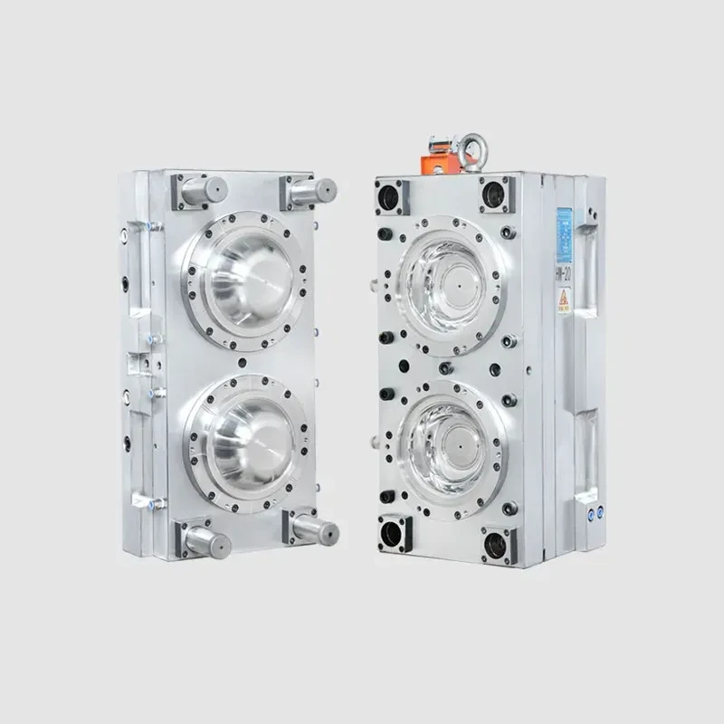
These design features are then passed to simulation tools for validation and to CAM systems for machining. In practice, CAD helps the mold designer coordinate functional constraints that are difficult to manage reliably with manual drafting alone.
Technological Innovations and Automation
Modern CAD systems are increasingly tied to digital manufacturing workflows. Important innovations include:
- CAD/CAM integration, which allows digital design data to become machine instructions for CNC machining.
- CAE coupling, which supports simulation of structural, thermal, flow, and motion behavior before tooling is made.
- Virtual prototyping, which reduces dependence on multiple physical prototypes.
- Automation features, such as automated dimensioning, specification checks, and reusable libraries.
- Cloud collaboration, which improves revision control across design, tooling, and production teams.
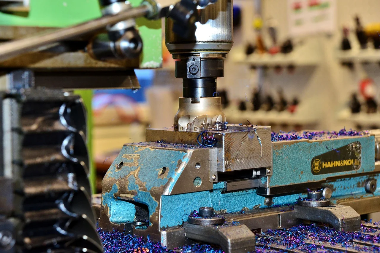
For plastics processors, these capabilities help reduce lead time between product concept and first article approval, especially when tooling changes are expensive and production schedules are tight.
Environmental and Sustainability Aspects
CAD systems contribute to sustainability mainly by reducing waste and improving design efficiency. Because geometric and process issues can be identified earlier, fewer defective molds, short-shot parts, or misaligned tool components reach production.
Key sustainability benefits include:
- Reduced material waste through optimized geometry and better manufacturing preparation.
- Lower prototype consumption by replacing some physical iterations with digital simulation.
- Improved tooling efficiency, which can reduce scrap during start-up and process tuning.
- Support for lightweighting, where optimized part design lowers resin use without sacrificing function.
The sustainability value is not automatic, however. CAD systems also increase reliance on digital infrastructure, training, and software ecosystems, so their environmental benefit depends on how effectively they are used in the full product-development chain.
Economic and Global Market Impact
CAD systems are a major economic enabler across the plastics industry because they reduce design time, improve coordination, and help move products into production more quickly. In tooling-intensive sectors, this can materially affect time to market and competitiveness.
Their market impact is strongest where:
- Tooling costs are high
- Product cycles are short
- Precision requirements are strict
- Global design and manufacturing teams must collaborate across sites
CAD also supports reuse of standard parts and design libraries, which improves consistency and lowers engineering effort across product families. For plastics machinery producers and mold makers, this creates a compounding advantage: better digital design typically leads to better manufacturability, which in turn improves utilization of capital equipment and reduces downstream corrections.
Current Challenges and Innovations
Despite their maturity, CAD systems still face several challenges in plastics engineering.
- Interoperability remains a recurring issue when files move between different software environments and suppliers.
- Model fidelity can be limited when the CAD model is not aligned with process realities such as shrinkage, cooling asymmetry, or material anisotropy.
- Skill requirements are substantial, especially for surface modeling, mold design, and digital manufacturing integration.
- Data management becomes difficult as assemblies, revisions, simulation files, and manufacturing outputs multiply.
Current innovation is focused on:
- Better integration with simulation and process validation
- More intelligent feature recognition for manufacturing
- Expanded use of cloud-based collaboration
- Improved automation of routine drafting and documentation
- Tighter links between CAD geometry and machine-readable manufacturing data
Future Outlook
The future of CAD systems in plastics processing is likely to be shaped by deeper integration with simulation, automation, and lifecycle data. Rather than acting only as design tools, CAD platforms are becoming digital engineering hubs that connect product definition, tooling, process planning, and manufacturing execution.
The most important developments are likely to be:
- Generative and algorithm-assisted design for lightweighting and manufacturability
- More direct CAD-to-machine workflows for tooling and fixtures
- Greater use of model-based definition, where geometry and tolerances are embedded in the 3D model rather than duplicated across drawings
- Stronger support for multi-site collaboration and supplier networks
- Wider adoption of digital twins linking design intent to processing performance
For plastics manufacturers, these changes should improve the ability to design parts and equipment that are easier to mold, faster to validate, and more efficient to produce.
Summary
CAD systems are foundational tools in plastics engineering because they connect product geometry, tooling design, analysis, documentation, and manufacturing preparation in one digital environment. Their evolution from drafting software to integrated design platforms has made them essential for injection molding, extrusion, blow molding, thermoforming, and mold making, while also supporting sustainability, automation, and faster product development.
References
- •
Computer-aided design. (2001, July 26). In Wikipedia. https://en.wikipedia.org/wiki/Computer-aided_designLink
- •
What is CAD? Understand CAD: A comprehensive guide. (2025, September 10). Autodesk. https://www.autodesk.com/blogs/autocad/what-is-cad/Link
- •
Modern CAD/CAE/CAM tools and their applications. (n.d.). University of Victoria. https://www.engr.uvic.ca/~mech410/old/2_Lecture_Notes/1_CADCAECAM_Review-SM.pdfLink
- •
What is CAD? Computer-aided design (CAD). (2022, April 29). PTC. https://www.ptc.com/en/technologies/cadLink
- •
What is CAD? A beginner’s guide. (2024, September 30). Coursera. https://www.coursera.org/articles/what-is-cadLink
- •
Real-world uses of CAD software & 3D scanning. (2022, July 29). Artec 3D. https://www.artec3d.com/learning-center/real-world-uses-of-cadLink
- •
Applications of CAD technology. (2013, March 10). SlideShare. https://www.slideshare.net/slideshow/ss-17092757/17092757?nway-content_model=ALink
- •
CAD systems. (2025, January 20). Ismy. https://www.ismy.net/archive/cad-systemsLink
- •
What is CAD (computer-aided design)? (2025, January 24). TechTarget. https://www.techtarget.com/whatis/definition/CAD-computer-aided-designLink
- •
CAD software for manufacturing: Uses and benefits. (2023, August 18). RS Components. https://www.rs-online.com/designspark/the-use-of-cad-in-manufacturingLink
- •
Advantages of computer-aided design. (n.d.). Drexel University. https://drexel.edu/cci/stories/advantages-and-disadvantages-of-cad/Link
- •
What are the benefits of using CAD software? (n.d.). PTC. https://www.ptc.com/en/blogs/cad/what-are-the-benefits-of-using-cad-softwareLink
- •
CAD (computer-aided design) types and uses. (2024, September 17). Spiceworks. https://www.spiceworks.com/tech/devops/articles/what-is-cad/Link
- •
Advantages of computer-aided design (CAD) software. (2024, May 23). i GET IT. https://myigetit.com/tech/advantages-of-computer-aided-design-cad-software/Link
- •
The advantages of using CAD software. (2023, August 1). Fractory. https://fractory.com/cad-advantages/Link
- •
Computer aided design (CAD): Definition, types and use. (2024, March 15). Xometry. https://www.xometry.com/resources/3d-printing/cad-modeling/Link
- •
Computer-aided architectural design. (2005, May 19). In Wikipedia. https://en.wikipedia.org/wiki/Computer-aided_architectural_designLink
- •
Introduction. (n.d.). MVJ College of Engineering. https://mec.edu.in/mvlc/ppt/l_mech/ppt_cim.pdfLink
- •
What is CAD, computer-aided design? (n.d.). Spatial. https://www.spatial.com/glossary/cadLink
- •
The advantages of CAD. (2022, February 3). Cad Crowd. https://www.cadcrowd.com/blog/the-advantages-of-cad/Link
- •
CAD/CAM software for design & manufacturing. (2024, July 29). Autodesk. https://www.autodesk.com/ca-en/solutions/cad-camLink
- •
Syllabus. (n.d.). Guru Jambheshwar University of Science and Technology. https://gjust.ac.in/portal/upload/E-Content%20on%20CAD_25March2026_18-20-24-91.pdfLink
- •
What is CAD technology? Applications and future trends. (2026, August 27). Neural Concept. https://www.neuralconcept.com/post/the-future-of-cad-technology-innovations-and-implicationsLink
- •
What is CAD (computer-aided design)? (2021, April 27). Autodesk. https://www.autodesk.com/products/fusion-360/blog/what-is-cad-computer-aided-design/Link
- •
Advantages and disadvantages of using computer aided design (CAD). (2018, September 29). Arcvertex. https://www.arcvertex.com/article/advantages-and-disadvantages-of-using-computer-aided-design-cad/Link
- •
Computer aided dispatch systems. (n.d.). U.S. Department of Homeland Security. https://www.dhs.gov/sites/default/files/publications/CAD_TN_0911-508.pdfLink
- •
Computer-aided dispatch (CAD): Definition, benefits & use cases. (2025, September 25). Getac. https://www.getac.com/us/industries/public-safety/computer-aided-dispatch/Link
- •
7 benefits of computer aided dispatch (CAD) systems. (2024, October 22). Gina Software. https://www.ginasoftware.com/blog/computer-aided-dispatch-benefits/Link
- •
7 industries that use computer aided design (CAD). (2024, February 7). Charter College. https://chartercollege.edu/news-hub/7-industries-that-use-cad/Link
- •
Advantages of CAD in design and presentation. (2023, June 26). Tacton. https://www.tacton.com/cpq-blog/advantages-of-cad-2/Link
- •
CAD software: 2D and 3D computer-aided design. (2026, April 10). Autodesk. https://www.autodesk.com/solutions/cad-softwareLink
- •
CAD design software. (2026, August 4). Autodesk. https://www.autodesk.com/solutions/cad-designLink
- •
What’s the advantages of CAD. (n.d.). Reddit. https://www.reddit.com/r/AutoCAD/comments/34uld1/whats_the_advantages_of_cad/Link
- •
What is CAD software? 3D design. (2026, July 6). Dassault Systèmes. https://www.3ds.com/technologies/cad-softwareLink
- •
What is CAD (computer-aided design)? A beginner’s guide. (2025, April 4). Six Sigma DSI. https://sixsigmadsi.com/computer-aided-design-cad/Link
- •
CAD software: 2D & 3D computer-aided design. (2026, April 6). Dassault Systèmes. https://www.3ds.com/store/cadLink
- •
Best computer-aided design (CAD) software reviews 2026. (2025, January 1). Gartner. https://www.gartner.com/reviews/market/cad-softwareLink
- •
Computer-aided design (CAD). (n.d.). Siemens. https://www.siemens.com/en-us/technology/computer-aided-design-cad/Link
- •
19 types of CAD software: Definition, lists and benefits. (2026, June 16). Indeed. https://sg.indeed.com/career-advice/career-development/cad-softwareLink
- •
Computer-aided dispatch. (2003, December 17). In Wikipedia. https://en.wikipedia.org/wiki/Computer-aided_dispatchLink